Let us look at a typical variable air volume (VAV) supply air system as laid out in Figure 1. It requires 20,500 cfm at 3 inches w.g. static pressure, which includes 400 cfm or 2 percent estimated duct air leakage. The VAV boxes need a minimum of 1 inch w.g. at the box inlet. Rectangular and flat oval duct aspect ratios cannot exceed 3:75 to 1. Ductwork shall be sealed as per SMACNA Seal Class B for 3 inch w.g. and Class C for 2 inch w.g. construction pressure classifications. All elbows will have R/D = 1.5, transitions = 30 degree slope, branch taps = 45 degree angle with 45 degree elbows, and wye fittings = 45 degree angles with 45 degree elbows. All duct branches to VAV boxes have balancing dampers. All ductwork will be galvanized steel with gauges and reinforcements as per SMACNA HVAC Duct Construction Standards-2005 edition.
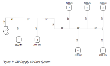
The system in Figure 1 was done in three different ways each to have approximately the same static pressure drop. Firstly, round spiral duct in 32 inch diameter to 14 inch diameter, flat oval and spiral 60”x16” to 14” diameter, and then rectangular duct 60”x16” to 12”x14”.
Duct Construction
Round: 22 gauge spiral duct from fan to 28 gauge spiral duct for the end branch ducts. No extra reinforcement required with spiral coupler joints.
Flat Oval: 20 Gauge flat oval duct from the fan to 28 Gauge spiral round ducts for the end branch ducts. F-20 reinforcement used on 4 foot centres for only the flat surfaces.
Rectangular: 18 gauge duct from the fan with H-18 reinforcement plus F+Rod intermediate reinforcement to 22 gauge with no reinforcement.
Duct Leakage Calculations
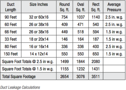
Duct system air leakage is based on the amount of total duct surface and leakage classes established by SMACNA/ASHRAE research (see Table 4.1). Round duct has the smallest perimeter per air volume. Flat oval and rectangular are larger in that order.
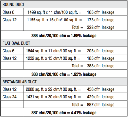
From the above calculations we can see that the rectangular duct exceeds the original estimated leakage of 400 cfm by an additional 487 cfm, so the sample duct section would now require 21,000 cfm from the supply fan. This increase in fan volume will cause slight increases in system velocities and static pressures. To be prudent, the designer should increase the initial rectangular duct pressure classification to 4 inches w.g. to allow for pressure increases that could occur with system balancing, as the calculated system static pressure drop was 2.98” w.g.
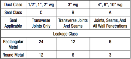
The changes to a 4” w.g. rectangular pressure class would also reduce leakage by half because of the “A seal class”. So it can be seen that different types of duct systems each come with inherent factors and the designer must look to find the best solution for the design at hand.
References:
Spiral Duct Manufacturers Design Guide.
2007 SMACNA Duct Leakage Paper 12/92
ASHRAE Fundamentals Handbook 2009